

A ball grid array hides every solder joint underneath the package, so you cannot simply look at the result and know the board is good. That is what makes BGA assembly both powerful and demanding. BGAs give you high pin counts in a small footprint with short electrical paths, but they need a well-controlled process and the right inspection to catch hidden defects. Here is how BGA joints form, what goes wrong, and how X-ray inspection fits in.
Why BGA Assembly Needs Extra Care
In a BGA, the connections are solder balls arranged in a grid on the underside of the package. During reflow the balls melt together with the solder paste printed on the pads and collapse into joints between the package and the board. Because the joints sit under the body, the process has to get several things right at once: paste volume, placement accuracy, a suitable thermal profile and dry, undamaged parts.
Fine-pitch BGAs leave little margin. Smaller balls and pads mean less paste per joint, and a small variation in print or heating can be the difference between a good joint and a marginal one.
Common BGA Assembly Defects
Most BGA problems fall into a short list:
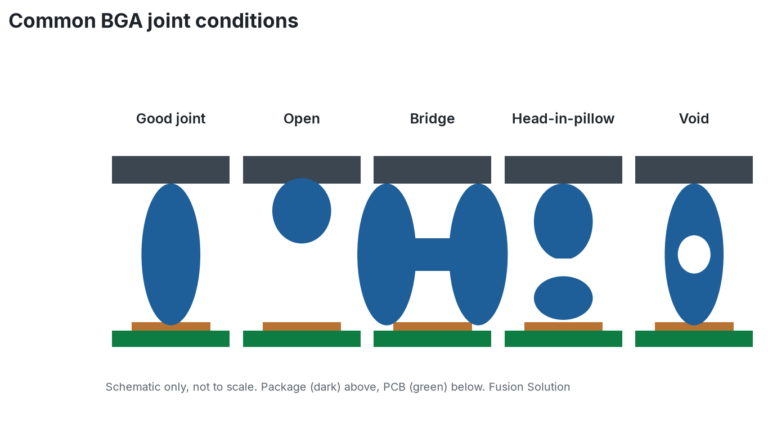
- Bridging (shorts). Too much paste or poor spacing lets solder join neighbouring balls.
- Opens. A ball never wets the pad, often from warpage, poor paste transfer or contamination.
- Head-in-pillow. The ball and the paste deposit touch but never fully merge, leaving a joint that looks formed but is weak. It can pass electrical test at first and fail later.
- Voids. Gas trapped in the joint during reflow. Small voids are common and often acceptable, while large or clustered voids can reduce strength and heat transfer.
- Cracks and popcorning. Damage from trapped moisture, which is why handling of moisture sensitive components matters so much for BGAs.
Inspecting BGA Assembly with X-ray
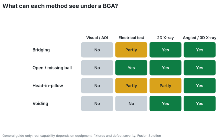
Automated optical inspection and visual checks only see the edge of the package, and electrical test confirms connectivity but can miss a marginal joint. X-ray inspection looks through the package and shows the balls directly. It is the standard way to check hidden joints.
- 2D X-ray. A fast top-down view that shows ball alignment, bridging, missing balls and voiding as a percentage of ball area.
- Angled or 3D X-ray. Views from several angles help reveal head-in-pillow and other defects that a flat image can hide.
- Acceptance criteria. IPC-A-610 sets workmanship criteria, including limits on voiding in BGA balls, and the right limit depends on your product class and customer requirements.
X-ray is most valuable during first-article builds and process setup. Once the profile and print are proven, many teams switch to sampling while keeping electrical test on every board.
Designing for Reliable BGA Assembly
Good results start in layout. Match pad sizes to the manufacturer recommendation, choose a stencil aperture that delivers the right paste volume (see our notes on solder paste types), and keep the board flat with balanced copper and a suitable thickness. Plan escape routing and via placement early, and tell your assembler which surface finish and tolerance you need. A well-set reflow heat curve then does the rest.
Our BGA Assembly Approach at Fusion Solution
At Fusion Solution we review BGA footprints and stencil apertures before the first build, confirm the moisture sensitivity of each part, and verify placement and joint quality on first articles using X-ray inspection. This follows the same thinking as design for manufacturability, and it helps boards assembled in Calgary reach production without hidden defects.
Ready to Build with BGAs?
If your design uses BGAs and you want a reliable, inspected build, we can help. Talk to Fusion Solution about our PCB design and assembly services and we will plan the build around your parts.